Temperature Interlock (UNDER CONSTRUCTION)
Bart Hommels, Saevar Sigurdsson
Introduction
This page contains information on the Interlock unit provided for the ATLAS SCT Upgrade. Its main purpose is to protect the ATLAS SCT Upgrade Modules from overheating due to any kind of failure or error condition by cutting off the power supply to the hybrid.
Main Features
- 3 independent Temperature sensor groups:
- 8 Hybrid NTCs: H0-7
- 2 User NTCs: U8-9
- 1 SHT-7x digital Temperature and Relative Humidity sensor
- Individual Temperature limits, enable mask, averaging filter, and NTC parameter set for each group
- All settings are made accessible through a display-driven menu, operated through a single dial/push dial
- Settings are stored in non-volatile memory (EEPROM)
- Two switched mains channels, and one floating relay output
Sensor connections
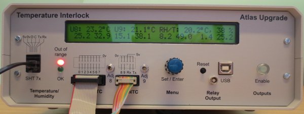
NTCs are connected to the front-panel IDC connectors, one per vertically arranged pair of pins. The trimpots located next to the U8-U9 IDC connector can be used to calibrate the readings using a reference resistor, or the NTC at reference temperature.
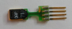
The SHT-71, or SHT-75 sensor connections are routed through the RJ11 socket. Clicking on the SHT sensor picture on the right brings up a connection diagram. Counting from the left, pin 1, and 2 carry +5V, and GND respectively. Subsequently, pin 3 is labeled D for Data, and pin 4 is C for Clock. The required 10kOhm pull-up resistor, from D to +5V, is incorporated in the unit.
Front Panel Controls
LEDs and Pushbuttons
When at least one sensor is connected, enabled, and its temperature readings are in the range defined, the green LED on the left is lit. In any other case, the red LED is on.
The enable button on the right is off when the red LED is on. If the green LED on the left is lit, the enable button on the right is blinking. Upon pressing the button, the outputs are enabled and the enable button LED is on continuously.
The reset button will disable all outputs and reboot the unit processor.
Dial/Push dial
The central dial/push dial sets what is printed on the display top line, and is used for menu control, see below.
Display and Menu Operation
The default is that the menu is inactive. Pressing the dial knob, irrespective of the dial position, will activate the menu.
The content of the display top line depends on the dial knob position, and whether the menu is activated.
On the bottom line of the display, the temperature readings of the H0-7 NTCs are displayed, when enabled. Otherwise, the U8-9, and SHT-7x sensor readings, if enabled, are displayed.
Menu Inactive:
| Dial position | Display top line parameters |
|---|---|
| Leftmost position: | H0-7 NTC parameters |
| Left of middle: | H0-7, U8-9 NTC Temperature Limits |
| Middle position: | H0-7 indicators |
| Right of middle: | U8-9 & SHT-7x Temperature, and Relative Humidity readings |
| Right: | SHT-7x Temperature & Relative Humidity limits |
| Rightmost: | U8-9 NTC parameters |
Menu Active:
The top line displays the options for a particular menu stage. The selected option is CAPITALISED. Upon pressing the knob, the menu is advanced, activating the capitalised selection. The menu state machine is only advanced upon pressing the knob, never automatically. When the knob is not pressed for 2 minutes, a watchdog timer will deactivate the menu.


