Temperature Interlock Relay switch, Jumper settings
Bart Hommels, Saevar Sigurdsson
Relay switch
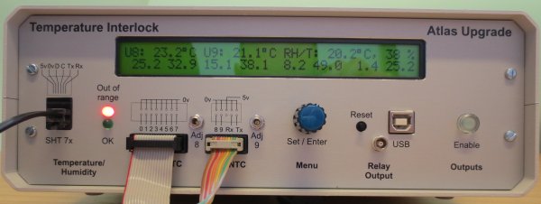
In addition to the mains outputs, an internal relay is engaged upon enabling the interlock. Its original purpose is to inhibit the custom current source as developed by the Prague Group/Jan Stasny. As both of its contacts are floating it can be used for other purposes.
The relay is an OMRON-G5V-1, maximum switching voltage 125 VAC/24 VDC, and 1A maximum current. Please note that the optional 51 Ohm terminating resistor (see below) has very limited maximum dissipation.
Jumper Configuration
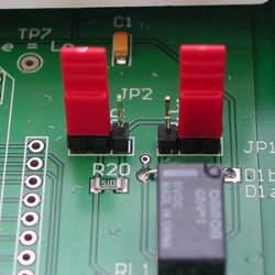
The relay switch is behaviour is configured by two internal jumpers. The jumper location is illustrated by the middle photo on the right. The lower picture illustrates the jumper labeling, and pin positions. The first jumper, JP1, determines whether the relay contact is normally open (NO), or normally closed (NC). JP2 sets the closed contact resistance to 0, or 51 Ohm. The following table contains the settings for each jumper position, according to the viewpoint of the picture:
| Jumper Position | Left | Right |
|---|---|---|
| JP1 | Normally Closed | Normally Open |
| JP2 | 51 Ohm | 0 Ohm |


