Temperature Interlock Serial Commands (UNDER CONSTRUCTION)
Bart Hommels, Saevar Sigurdsson
Interlock Serial Communications Channel
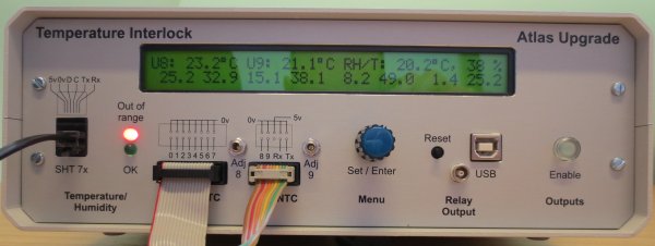
The Interlock Unit is based on the Arduino Uno platform, which has a USB connection that serves as a serial interface. It can be used to read out the sensor data, as well as sending commands to request readings, change settings, etc (see below). Upon a state change, sensor readings as well as the output state are sent. Disabled sensors readings are set to -99.9 (deg C).
Serial Interface: Serial over USB
On Windows, the ArduinoUNO.ini file is needed to initialise the serial connection with the Arduino chipset. The install procedure is described here. Once the driver is installed, any tty tool for windows can be used to address the unit. Although the arduino environment has a 'Serial monitor' built in, putty works fine as well.
On linux/Unix, a description of how to talk to Arduino can be found here. The interlock operates at 115200 baud, and needs CR at the end of each line.
Serial Command Format
Serial commands consist of a string of 3 characters, followed by a comma, followed by an integer number of up to 4 digits in length. Two types of commands are implemented: specific commands, addressing one or more of the sensor settings in particular, and generic commands.
Generic Commands
For generic commands, that are not addressing one or more of the sensors, the integer number following the command string must be 100.
| Command | Integer | Description |
|---|---|---|
| idr | 100 | Interlock Data Request |
| irs | 100 | Interlock Read Settings |
| ena | 100 | Interlock Output Enable |
| dis | 100 | Interlock Output Disable |
| wre | 100 | Write current Settings to EEPROM |
Specific Commands
The specific commands set a parameter that applies to a sensor group. The integer number is checked against the expected range, and then set accordingly. The first character of the command indicates the group:
| Character | Sensor Group |
|---|---|
| h | Hybrid NTCs: H0-7 |
| u | User NTCs U8-9 |
| r | SHT 7x RH/T sensor |
The second, and third character of the command refer to the parameter of the sensor group that is set, and is encoded as follows:
| Command | Integer Range | Description |
|---|---|---|
| tl | Lower Temperature Limit | -25..75 for NTCs, -40..99 for the SHT7x |
| th | Higher Temperature Limit | -25..75 for NTCs, -40..99 for the SHT7x |
| ne | Number of sensors Enabled | 0..8 for H0-7 NTCs, 0..2 for U8-9 NTCs, 0,1 for the SHT7x |
| na | Number of samples for averaging filter on NTC readings | 0..8 |
| rn | Nominal NTC Resistance (at Nominal Temperature) in kOhm | 1,10 for H0-7, 1/2/3/5/10/20 for U8-9 |
| tn | Nominal NTC Temperature in deg C | 20, 25 |
| bn | NTC B parameter in deg K | 3000..4000 |
| rl | Lower relative humidity limit for SHT7x sensor | 0..100% |
| rh | Higher relative humidity limit for SHT7x sensor | 0..100% |
Examples
una,4 will set the number of samples used for averaging the measurements on the U8-9 NTCs to 4.
htl,-10 will set the lower temperature limit for H0-7 to -10 degrees Centigrade.
An example file containing the commands to set up the Interlock Unit for operation with a chilled-water cooled single module can be found here.


